How to Design Inverter for Solar Power System | Step-by-Step Guide
Solar power is a leading force in renewable energy. But how does it work for our homes? The key lies in the inverter. This device transforms the direct current (DC) electricity from solar panels into the alternating current (AC) electricity that powers our appliances.
While pre-built inverters are readily available, designing your own can be a fun challenge for tech enthusiasts. It offers a deeper understanding of solar systems, potential cost savings, and a custom-built solution. However, designing inverters involves high voltages and currents, so it’s necessary to measure safety precautions.
How to Design an Inverter for Your Solar Power System?
Before starting, let’s plan your solar system. We’ll figure out how much power you need from appliances and choose the right inverter for your solar panels (voltage, grid connection). Then we’ll explore the technical details of inverters, from input/output specs to efficiency and quality. So, without any further ado, let’s begin!
System Planning
First of all, let’s understand your power requirements. List all your appliances and their wattage. Some devices, like LED lights or phone chargers, can use DC directly. This can influence your inverter design or even eliminate the need for an inverter in certain parts of your system.
Multiply each appliance’s wattage by its daily usage hours. A 100W light bulb used for 5 hours consumes 500 watt-hours. Sum these up for your total daily energy need.
Next, ensure your inverter matches your solar setup. Solar panels typically output 12V, 24V, or 48V DC. Their current (amperes) depends on panel size and efficiency. For instance, a 250W panel at 24V would produce about 10A (250W ÷ 24V).
Your inverter’s input voltage range must accommodate your panel voltage. If you have 24V panels, choose an inverter that accepts 24V input.
NOTE: Grid-tied systems connect to the utility grid, allowing you to sell excess power. Off-grid systems are standalone and often include battery storage. Your choice impacts inverter design, especially regarding safety features and grid synchronization for grid-tied systems.
Electrical Specifications
The electrical specifications are important to ensure that your inverter can safely and efficiently convert the DC power from your solar panels into usable AC power for your home.
So, ensure voltage range and current rating. If your panels output 24V, your inverter should accept 20-30V to account for voltage fluctuations. Similarly, if your panels can output 20A, your inverter should handle at least 20A. It’s wise to add a safety margin, so consider an inverter rated for 25A or more.
For your information –
- In the U.S., the standard home voltage is 120V. Some appliances like dryers or ovens may need 240V.
- The U.S. uses 60Hz. Europe and many other countries use 50Hz. Ensure your inverter outputs the correct frequency for your appliances.
- Most homes use single-phase power. Larger installations like farms or factories might require three-phase power.
Efficiency and Quality Factors
Efficiency and quality are the hallmarks of a well-designed solar inverter. A highly efficient inverter minimizes power losses, translating to more usable energy and lower electricity bills.
Efficiency
High-quality inverters boast 95%+ efficiency. This means if your panels generate 1000W, at least 950W becomes usable AC power. Lower efficiencies waste power as heat.
The Maximum Power Point Tracking (MPPT) feature dynamically adjusts the inverter’s input characteristics to extract maximum power from your panels under varying conditions. It can boost system efficiency by 20-30%.
Quality
The Total Harmonic Distortion (THD) measures how closely your inverter’s AC output matches a perfect sine wave. High THD can damage sensitive electronics. Aim for THD < 5%.
Also, look for features like robust heat sinks, high-quality capacitors (like Japanese brands), and conformal coating on PCBs to resist humidity. These ensure your inverter lasts 10-15 years or more.
Inverter Design Fundamentals
The core of an inverter is the DC-to-AC conversion process. It involves switching DC on and off rapidly to create a square wave, then filtering this to approximate a sine wave. Common topologies include –
Full-bridge: Uses four switches (often MOSFETs or IGBTs) to create a bipolar square wave. It’s efficient and provides full utilization of the transformer core, but requires complex control.
+—–+
| |
Q1 Q3
+12V —+ +— AC Output
Q2 Q4
| |
+—–+
|
GND
In this circuit –
- Q1, Q2, Q3, Q4 are MOSFETs or IGBTs.
- Q1 and Q4 switch on together, then Q2 and Q3, creating a bipolar square wave.
- A transformer (not shown) steps up the voltage and helps filter to a sine wave.
Half-bridge: Uses two switches and a capacitor divider. It’s simpler than full-bridge but requires higher voltage components and has lower transformer utilization.
Push-pull: Uses two switches and a center-tapped transformer. It’s good for low-voltage, high-current applications but suffers from transformer core saturation issues.
Component Selection
The performance of your inverter depends heavily on the quality and compatibility of its components.
Power Semiconductors: MOSFETs are great for low-voltage (<200V), high-frequency applications due to their fast switching. IGBTs are better for higher voltages (>1000V) and currents. For a 24V, 2000W inverter, you might use four 100V, 50A MOSFETs in a full-bridge configuration.
Capacitors and Inductors: Use high-frequency, low-ESR (equivalent series resistance) capacitors like multilayer ceramic or polypropylene film types. For inductors, ferrite or powdered iron cores minimize losses. A 2000W inverter might use a 10mH inductor and 1000µF capacitor for output filtering.
Resistors: Used in control and sensing circuits. Choose metal film resistors for stability and low noise.
Designing the Control Circuit
The control circuit is the brain of your inverter. It orchestrates the power conversion process, ensuring that the output is a stable, clean sine wave regardless of input fluctuations.
Microcontroller: An Arduino or ARM-based board (like STM32) can generate PWM signals. The STM32F4 series offers high-speed PWM ideal for inverters.
Sensor: Use hall-effect sensors for current (like ACS712 for up to 30A) and a voltage divider with an op-amp buffer for voltage sensing.
PWM: Generate high-frequency (10-20kHz) PWM to create a square wave. Vary the duty cycle sinusoidally to approximate a sine wave after filtering.
+5V
|
R1
|
Arduino D9 —–> MOSFET Gate (Q1)
|
GND
Here,
- Arduino’s D9 pin outputs a PWM signal.
- R1 (1kΩ) limits current to the MOSFET gate.
- PWM frequency and duty cycle control the inverter’s output waveform.
Building and Testing
Transforming your design from schematic to reality is an exciting yet critical phase. Building and testing demand patience and precision; a single overlooked detail can mean the difference between a functional inverter and a costly mistake.
Design your PCB with wide traces for power paths. Use a 4-layer board with inner layers for power and ground planes to reduce noise. Use insulated tools, work on a non-conductive surface. Start with low voltages and currents.
Use a multimeter and oscilloscope to check voltages, currents, and waveforms. Look for clean sine waves and expected voltage levels.
System Design and Integration
This section covers sizing your system components, strategic inverter placement for longevity, and the nitty-gritty of wiring and installation.
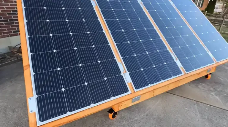
For a 2000W system, choose a 2500W inverter for headroom. If your panels output 250W each, you’d need at least 8 panels. Mount the inverter in a cool, dry place. Garages or utility rooms are good. Ensure at least 6 inches of clearance for ventilation. For a 24V system, use at least 4 AWG wires. Always follow local electrical codes.
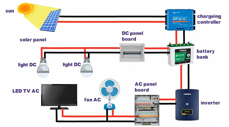
Here’s a diagram of a simple solar charging system with a buck converter for battery charging –
Solar Panel Buck Converter Battery Inverter
| | | |
+48V +—-+ +12V +—+
|—->| | | | | |
| |—–>| DC |———–>|———–>|AC |—> 120V AC
| | | | | |
GND +—-+ GND +—+
- The buck converter steps down 48V to 12V for battery charging.
- The battery powers the inverter during low-light conditions.
What Else to Consider While Designing an Inverter for Solar Power System?
There are a few things you need to consider especially while designing the inverter. Those are –
- Use synchronous rectification (replacing diodes with MOSFETs) in the full-bridge to reduce losses.
- Implement over-voltage, over-current, and over-temperature shutdowns in your microcontroller code.
- This requires anti-islanding protection (shutting off if grid power fails) and precise frequency matching. Consider starting with off-grid before tackling grid-tie.
Solar Panel Inverter Anti-Islanding Grid
| | Circuit |
+48V +—+ +—+ +—+
|—->| | | | | | |
| |—>|DC |———–>|AC |——>|AC |
| |AC | | | | |
GND +—+ +—+ +—+
- The anti-islanding circuit detects grid failure and shuts off the inverter.
- This prevents the inverter from feeding power into a down grid, which could harm utility workers.
- Use software like Proteus, LTspice, or MATLAB/Simulink to simulate your design. Simulate fault conditions like short circuits to test your safety features.
End Note
Designing a solar inverter is a challenging but rewarding project. It demands careful planning, component selection, and rigorous testing. Always prioritize safety and don’t hesitate to start small or seek professional help. With diligence and respect for the power you’re handling, you can create a custom heart for your solar power system, driving your journey towards sustainable, self-generated energy.
Frequently Asked Questions
Can I use a modified sine wave inverter instead of a pure sine wave for my home?
While modified sine wave inverters are cheaper, they can cause buzzing in audio equipment, flickering in lights, and may damage sensitive electronics like laptops or medical devices. Pure sine wave is recommended for home use.
How do I account for cloudy days in my inverter design?
Your inverter should handle variable input gracefully. Implement MPPT and consider oversizing your panel array by 20-30% to ensure adequate power even on cloudy days. Also, many systems include batteries to store excess energy for use during low-light conditions.
Is it legal to connect my DIY inverter to the grid?
Laws vary by location. In most areas, grid-tied systems must be certified (like UL 1741 in the U.S.) and installed by licensed professionals. DIY inverters are usually best suited for off-grid applications unless you have them professionally reviewed and approved.
![[Explored] Can You Use Mirrors To Redirect Sunlight On Solar Panels?](https://www.itekenergy.com/wp-content/uploads/2023/08/can-you-use-mirrors-to-redirect-sunlight-768x428.webp)
![[Explore] How Often Do Solar Panels Need to Be Replaced?](https://www.itekenergy.com/wp-content/uploads/2023/06/How-Often-Do-Solar-Panels-Need-to-Be-Replaced-768x428.webp)